World's Leading Pumps MFG,All Solutions For Industries Pumps

One Industries
All Pumps Solutions

About Us

Eu-Flo (Shanghai) Pump Industries Co., Ltd.

Company Overview

Eu-Flo (Shanghai) Pump Industries Co., Ltd. is a professional pump manufacturer based in China, dedicated to the design and manufacture of high-performance pumping solutions in full compliance with international technical standards, including ISO2858, ISO5199, EN733, API610, and ISO13709. With over 25 years of experience in the global industrial pump market, Eu-Flo has established a strong reputation for reliability, quality, and engineering excellence.

Global Reach & Export Markets

As a seasoned pump exporter, Eu-Flo serves a diverse and growing international clientele. Our products are exported to key markets across:

  • ASEAN(Southeast Asia)
  • Middle East
  • South America
  • Russia
  • South Africa
  • South Asia

Our global trade footprint reflects the trust and recognition we have earned from customers worldwide.

Core Competencies & Product Portfolio

Eu-Flo specializes in the engineering and supply of a comprehensive range of industrial pumps, covering water and seawater, wastewater, petroleum and chemical liquids, oil and gas, food processing, and mining applications. Our product categories include:

  • Axially split case pumps (single-stage and multistage)
  • API 610-compliant pumps of all types
  • End suction pumps
  • Closed-coupled pumps
  • Vertical inline pumps
  • Multistage ring section pumps (horizontal and vertical)
  • Axial flow and mixed flow pumps
  • Slurry pumps
  • Submersible pumps
  • Self-priming pumps
  • ANSI Chem

Specialty Tailor-Made Pumps

One of Eu-Flo’s key strengths lies in our ability to design and manufacture specially tailored pumps to meet unique project requirements. Our expertise includes a full range of vertical suspended pumps, such as:

  • VS1– Single-stage vertical suspended pump for large flow, low-head applications
  • VS2– Single-stage vertical suspended pump
  • VS3– Multistage diffuser-type vertical pump for high-head applications (up to 400+ meters)
  • VS4, VS5, VS6– Additional configurations for specialized vertical pumping needs

Key Application Sectors

Eu-Flo pumps are engineered for demanding industrial environments and are widely deployed in:

  • Oil Refineries– Handling petroleum, chemical liquids, and hydrocarbon processing
  • Power Plants– Critical pumping for cooling, boiler feed, and auxiliary systems
  • Marine & Offshore– Ballasting, bilge, and offshore platform applications
  • Industrial & Mining Operations– General industrial fluid handling and mineral processing

Quality Philosophy & Mission

Quality is the soul of our enterprise. At Eu-Flo, we are committed to manufacturing excellence, rigorous quality control, and continuous improvement. Our mission is “Forwarding Forever” – a dedication to innovation, progress, and staying ahead of industry demands.

Partnership Vision

Eu-Flo believes in building lasting partnerships. We are eager to work hand-in-hand with contractors, engineers, and project developers to turn shared visions into reality. Together, we can deliver reliable, efficient, and customized pumps solutions that drive project success around the globe.

Our Products

Slurry Pump for Chemical,Minerals,Pulp

API Pumps

Axially Split Casing Pumps

Self-Priming Pumps

Multistage Centrifugal Pumps

ISO End-Suction Pumps

Fire Fighting Pumps

Submersible Sewage Pumps

Industrial Process Esp Paper and Pulp of abrasive corrosive solid particles

Petroleum & Chemical

Boiler Feed For Power Plant

Fire Fighting

Water and Wastewater Treatment

The only place where you’ll get the perfect solution for all your industry Pump needs.

Our Contributions

Industries We Serve!
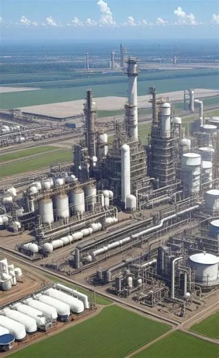
oip c 5

Oil And Refinery

Pump Applications in the Oil and Refining Industry: Upstream, Midstream, and Downstream
API Pumps are fundamental to the oil and gas industry, serving as the mechanical heart that moves liquid from the reservoir to the end-user. Their applications are broadly categorized into three sectors: Upstream (exploration and production), Midstream (transportation and storage), and Downstream (refining and processing). Each sector presents unique challenges, from handling abrasive, solids-laden crude to moving volatile, high-temperature hydrocarbons, requiring distinct pump technologies.

Upstream: Exploration and Production
The upstream sector involves the extraction of crude oil and natural gas from underground reservoirs. Pumping applications here are critical for well stimulation, artificial lift, and initial fluid transfer.

Key Applications & Pump Types
Application Description Common Pump Types
Water & CO₂ Injecting water or CO₂ into reservoirs to maintain pressure and enhance oil recovery (EOR). Requires high-pressure, reliable pumps . High-pressure centrifugal pumps (API 610 BB5), Positive Displacement Pumps .
Chemical Injection Precisely injecting production chemicals like methanol, glycol, and corrosion inhibitors into the well stream to prevent hydrates and manage flow . Metering pumps, Diaphragm pumps, Peristaltic pumps .
Crude Oil Transfer & Gathering Moving extracted crude oil from wellheads to central gathering stations or treatment facilities, often handling fluids with high solids and gas content . Progressing Cavity Pumps (PC Pumps), Rotary Lobe Pumps, Multiphase pumps .
Artificial Lift Using downhole pumps to lift oil to the surface when reservoir pressure is insufficient . Downhole PC Pumps (PCPs), Electrical Submersible Pumps (ESPs) .
Pumps used upstream must often handle challenging fluids containing sand, gas, and water, making durability and solids-handling capability key selection criteria .

Midstream: Transportation and Storage
The midstream sector bridges the gap between production and refining, focusing on the safe and efficient transport of crude oil and refined products via pipelines, as well as storage operations.

Key Applications & Pump Types
Pipeline Transfer: This is the primary function of midstream pumping, maintaining a steady flow of crude oil from production sites to refineries, and moving refined products to distribution centers . Long-distance pipelines require powerful, high-efficiency pumps .

Common Pump Types: High-pressure multistage centrifugal pumps (API 610 BB3, BB5), which are known for their efficiency over a broad flow range .

Fluid Boosting: Over long distances, fluid pressure drops due to friction. Booster pumps are installed along the pipeline to re-pressurize the fluid and ensure consistent delivery .

Common Pump Types: Centrifugal pumps, often used in HPump systems, are reliable and efficient for this application .

Fluid Treatment & Storage: Pumps are used in gas processing plants to purify natural gas and remove impurities (e.g., sulfur, NGLs), and in tank farms to safely transfer hydrocarbons to and from storage facilities .

Common Pump Types: Centrifugal pumps, vertical turbine pumps (e.g., VS6/VS7), and other API 610-compliant pumps are typical .

The key challenges in midstream are ensuring long-term reliability and low lifecycle costs, as pipeline systems operate continuously over extended periods .

Downstream: Refining and Petrochemicals
The downstream sector involves the transformation of crude oil into valuable finished products like gasoline, diesel, jet fuel, and petrochemical feedstocks. This process is characterized by high temperatures, high pressures, and the handling of corrosive and hazardous fluids .

Key Applications & Pump Types
Application Description Common Pump Types
Process Unit Feed Charging crude oil into distillation towers (topping) and feeding secondary process units like Hydrocrackers (HCU) and Hydrodesulfurizers (HDS) . Heavy-duty process pumps (API 610 OH2, BB5), multistage barrel pumps .
Reflux & Side-stream Transfer Managing the flow of intermediate products between distillation columns and other processing units . Standardized chemical pumps, single-stage centrifugal pumps .
High-Temperature/Caustic Services Moving hot hydrocarbon streams, often exceeding 400°C, and handling sour water, amines, and other corrosive fluids containing H₂S and CO₂ . Specialized process pumps with advanced materials, vertical pumps (VS6) for specific services .
Utility Services Supporting plant operations with boiler feed water, cooling water circulation, and hot oil circulation for heating systems . Standardized utility pumps, multi-stage pumps for boiler feed .
Refinery pumps must be ruggedly built and comply with strict API 610 standards to ensure safety and reliability in extreme conditions .

Summary of Pump Selection by Sector
Upstream: Focus on durability and solids handling. Positive displacement pumps (PC, lobe, diaphragm) are preferred for challenging, viscous, or solids-laden fluids. High-pressure centrifugal pumps are used for injection and transfer .

Midstream: Focus on efficiency and reliability over a broad operating range. Centrifugal pumps, especially API 610 multistage designs, are the standard for pipeline transfer and boosting applications .

Downstream: Focus on robustness under extreme conditions and API compliance. A wide range of heavy-duty, high-temperature process pumps (both centrifugal and positive displacement) are employed to handle diverse refinery streams safely and efficiently

oil

Power Plant

In thermal power plants, pumps are essential auxiliary machinery that support the entire steam-water cycle. Among them, three types stand out as the most critical: Boiler Feed Pumps (BFP) , Circulating Water Pumps (CWP) , and Condensate Extraction Pumps (CEP) . While all are centrifugal pumps, each serves a fundamentally different function and demands distinctly different pump characteristics. This article examines the application, performance requirements, and design considerations for each type. 1. Boiler Feed Pump (BFP) Application The boiler feed pump is often described as the "heart of the power plant". Its function is to deliver high-pressure feedwater (a mixture of fresh makeup water and returned condensate) into the steam boiler. The water is then converted into high-pressure, high-temperature steam that drives the turbine to generate electricity. An unexpected stop of the BFP completely halts power generation, which is why these pumps demand an exceptionally high level of reliability. Key Pump Characteristics Parameter Typical Range Discharge Pressure 30 – 35 MPa (for supercritical/ultra-supercritical plants) Fluid Temperature 150°C – 210°C (up to 250°C in some designs) Flow Rate Up to 500 m³/h per pump (larger units available) Drive Power Up to 9,000 kW for large units Design and Operational Requirements High Pressure, Multi-Stage Construction: BFPs must generate extremely high discharge pressures to overcome boiler operating pressure. This is achieved through multi-stage centrifugal pump designs with multiple impellers arranged Staggered. For supercritical and ultra-supercritical plants operating at 30–35 MPa, pumps typically feature double-casing (barrel-type) construction to contain the high internal pressures. High Temperature Capability: Feedwater temperatures can exceed 200°C. Pumps must be constructed with materials capable of withstanding thermal stresses, and external water cooling is often provided to manage heat. Reliability and Redundancy: Large power plants typically employ multiple BFPs in configurations such as 3×50% (three pumps, each capable of 50% capacity) or 2×100%. Typically, one motor-driven BFP is kept for startup and emergencies, while one or two turbine-driven BFPs handle normal full-load operation. Variable Speed Operation: With the increasing penetration of renewable energy, thermal plants are increasingly required to perform load-following duties. BFPs must accommodate rapid load changes, partial-load operation, and more frequent start-stop cycles. NPSH Management: To prevent cavitation, booster pumps are often installed upstream of the main BFP to raise suction pressure and satisfy NPSH requirements. 2. Circulating Water Pump (CWP) Application Circulating water pumps supply large volumes of cooling water to the steam turbine condenser. The cooling water condenses the exhaust steam from the turbine back into liquid water, completing the thermodynamic cycle. These pumps draw water from a freshwater source (river, lake, or cooling tower basin) or from the sea in coastal plants, circulate it through the condenser tubes, and discharge it back to the source or cooling tower. Key Pump Characteristics Parameter Typical Range Flow Rate Up to 90,000 m³/h (396,000 US gpm) Head Up to 60 meters (typically 18–22 meters) Temperature Up to 50°C Drive Power 1,275 – 1,900 kW Design and Operational Requirements High Flow, Low Head: CWPs are characterized by extremely high flow rates but relatively low discharge heads. The head requirement is primarily to overcome friction losses in the piping and condenser tubes, not to elevate water to great heights. Vertical Configuration: In medium to large power plants, CWPs are typically vertical column-type pumps. This design allows the pump to be installed in a wet pit or sump, with the motor located above ground and the impeller submerged in the water source. Large Impeller Diameter: CWP impellers can be up to 1,920 mm (76 inches) in diameter, reflecting the enormous flow capacities required. Mixed-Flow or Axial-Flow Design: To achieve high flow at low head efficiently, CWPs often employ mixed-flow or axial-flow impeller designs, which are more suitable than radial-flow designs for these operating conditions. Continuous Operation: CWPs typically run 24 hours a day, 7 days a week, with minimal downtime. Reliability and long maintenance intervals are therefore critical. Corrosion Resistance: When seawater is used as the cooling medium, pump materials must resist corrosion. Options include austenitic stainless steel, duplex, or super duplex materials. 3. Condensate Extraction Pump (CEP) Application Condensate extraction pumps collect saturated water (condensate) from the condenser hot well—where steam from the turbine has been condensed by the circulating water—and pump it forward through the low-pressure feedwater heaters to the deaerator. From the deaerator, the water proceeds to the boiler feed pump. Key Pump Characteristics Parameter Typical Range Flow Rate 170 – 4,900 m³/h Head 250 – 360 meters Fluid Temperature 25 – 35°C (at condenser hot well) Drive Power 460 – 1,600 kW Design and Operational Requirements Extremely Low NPSH Available (NPSHa): The most critical design challenge for CEPs is the extremely low Net Positive Suction Head available. The condenser operates under vacuum conditions, and the condensate is near its vapor pressure. To address this: CEPs are typically located at the lowest elevation in the power plant, often installed in a suction can below ground level, to maximize static head. The suction piping is designed to minimize frictional losses. Pumps are designed with a very low NPSH required (NPSHr) , often using a double-suction first-stage impeller or a high-suction-specific-speed single-suction first stage of VS2 Pump. Vertical canned (barrel) VS6 construction is commonly used to ensure adequate NPSHa. Multi-Stage Design: CEPs must raise the condensate pressure from near-vacuum conditions to the pressure required for the deaerator and low-pressure heaters (typically 250–360 meters of head). This is achieved through vertical multi-stage VS2 or VS6 construction. Sealing Integrity: Because the pump inlet operates under vacuum, any air leakage into the system can severely impair pump performance. Mechanical seals must be carefully designed and maintained. Design Margin: It is standard practice to size CEPs with a rated flow capacity of 120% of normal operating flow to accommodate off-design conditions and future degradation. Comparative Summary Characteristic Boiler Feed Pump (BFP) Circulating Water Pump (CWP) Condensate Pump (CEP) Primary Function Deliver water to boiler Supply cooling water to condenser Extract condensate from condenser Flow Rate Moderate Very High Moderate Discharge Head Very High (30+ MPa) Low (18–60 m) Medium (250–360 m) Fluid Temperature High (150–250°C) Ambient–50°C Low (25–35°C) Suction Condition Positive (with booster) Flooded suction Near-vacuum Key Challenge High pressure & temperature High flow capacity Low NPSH Typical Configuration Horizontal, multi-stage, barrel casing Vertical, single-stage, mixed-flow Vertical, multi-stage, canned Drive Power Very High (up to 9,000 kW) High (1,000–2,000 kW) Moderate (500–1,600 kW) Conclusion Boiler feed pumps, circulating water pumps, and condensate extraction pumps each occupy a distinct position in the power plant steam-water cycle, and each demands a unique set of pump characteristics. The BFP is a high-pressure, high-temperature, multi-stage pump built for extreme duty and uncompromising reliability. The CWP is a high-flow, low-head pump optimized for moving enormous volumes of cooling water efficiently. The CEP is a low-NPSH, multi-stage pump designed to operate under vacuum conditions and extract condensate from the condenser. Understanding these differences is essential for proper pump selection, operation, and maintenance in any thermal power generation facility
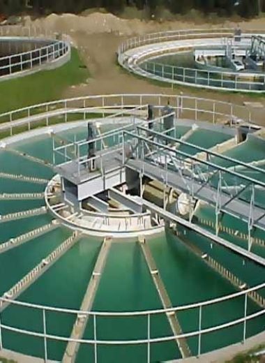
watertreatmentplant03

Water&Wastewater Treatment

Pumps are the Engine of every water and wastewater treatment facility moving, enabling the movement, pressurization, and circulation of fluids across countless process stages. However, no single pump type suits every duty. The selection of the right pump for each application requires careful evaluation of fluid properties, duty conditions, and system requirements—from raw water intake to final discharge. This article examines four key application areas: water source intake, wastewater circulation, water boosting, and seawater desalination, with a focus on the distinct pump characteristics each demands. 1. Water Source Intake Pumps Application Context Raw water intake is the first critical step in any water treatment process. Water may be drawn from rivers, lakes, reservoirs, groundwater wells, or aqueducts. The intake pump station must deliver raw water to the treatment plant at a capacity that matches plant design, often requiring multiple pumps operating in parallel to handle variable flow demands. Fluid Characteristics The key challenge at the intake stage is the variability of raw water quality. Source water may contain suspended sediment, sand, silt, fibrous material, biological matter, and other debris. Water quality can vary considerably in solids content, physical and chemical contaminants, temperature, and ecosystem composition. Pump Requirements and Characteristics Requirement Rationale Solids handling capability Must pass suspended particles without clogging or excessive wear Corrosion resistance Materials must match the chemistry of the source water Wide operating range Ability to handle fluctuating water levels and variable flow Wear-resistant construction Abrasive particles can rapidly damage conventional pump components Low NPSH requirements Suction conditions at intakes may be challenging Common Pump Types Submersible pumps: Preferred for rivers, dams, bores, and wet wells, particularly where water levels fluctuate significantly or civil infrastructure is limited. Their ability to operate across a wide range of submersion depths makes them practical for open water sources subject to seasonal variation. Split case pumps: Ideal for clean water applications, these Double-suction, between-bearings centrifugal pumps deliver high efficiency, long service life, and stable performance for moving large volumes of surface or groundwater. Their horizontally split design allows easy maintenance without dismantal piping. Vertical long-shaft pumps: Used for groundwater wells and applications requiring installation in confined spaces. Key Selection Considerations The first criterion is the source and quality of raw water. Intake pumps must be designed for pumping everything from screened, clear water to turbid water containing particulates. Proper screening arrangements are essential to protect pumps from damage. The number of pumps and their control strategy should maximize operating time in the preferred operating region to reduce total life cycle cost. 2. Wastewater Circulation Pumps (Process Recirculation) Application Context In biological wastewater treatment, recirculation pumps play a vital role in the activated sludge process, particularly in nitrification and denitrification. These pumps transfer nitrate-containing sewage from the nitrification basin back to the denitrification basin, where anoxic processes convert nitrates to nitrogen gas. They are also used for returning return activated sludge (RAS) to the activated sludge tank. Fluid Characteristics The fluid being pumped is activated sludge—a mixture of wastewater and microbial biomass. It has low to medium viscosity but contains suspended solids, fibrous materials, and debris. The medium temperature for continuous operation is typically up to 40°C. Pump Requirements and Characteristics Requirement Rationale Non-clogging design Must handle fibrous material and debris without blockage High volume flow, low head Recirculation involves moving large volumes with minimal elevation change Continuous operation reliability Pumps run 24/7 in critical biological processes Speed control capability Variable frequency drive operation supports load-sensitive control Corrosion-resistant materials Stainless steel propellers and flow housings resist aggressive wastewater Common Pump Types Submersible recirculation pumps: These are the preferred choice for wastewater recirculation. They feature submersible mixer designs with single-stage planetary gears and attached flow housings. Propellers are made from solid stainless steel with clogging-free geometry. Axial-flow propeller pumps: Designed for high flow rates (up to 4,500 m³/h) at very low heads (as low as 1.8 m), these pumps are optimized for moving large volumes of activated sludge between basins. Key Selection Considerations Impeller design is critical. Vortex and single-channel impellers are effective for passing solids without clogging, while chopper impellers address the rags and wipes increasingly common in modern sewage streams. Motor cooling is also essential in lift stations where low sump levels may limit fluid available to dissipate heat. Recirculation pumps are ideally suited for speed-controlled operation with frequency converters to support energy-efficient, load-sensitive control. 3. Water Boosting Pumps Application Context Pressure-boosting systems are essential for ensuring reliable water distribution in residential, commercial, municipal, and industrial applications. They address challenges of low water pressure in buildings, long-distance pipeline transmission, and elevation changes. Applications range from high-rise buildings requiring pressure to reach upper floors, to municipal distribution networks maintaining pressure across large service areas. Fluid Characteristics Boosted water is clean, treated potable water. However, the system demand is highly variable—hotels have peak usage in the morning, stadiums during breaks in play, and commercial buildings experience fluctuating occupancy. Pump Requirements and Characteristics Requirement Rationale Variable flow capability Demand fluctuates throughout the day High head capability Must overcome building height, friction losses, and required pressure Energy efficiency Pumps represent a major operating cost; efficiency is critical Reliability and redundancy Uninterrupted water supply is essential Compact footprint and low noise Space and noise constraints in buildings Potable water compliance Materials must meet NSF/ANSI 61 standards Common Pump Types Multistage centrifugal pumps: Two or more impellers working in staged on the same shaft. Each stage boosts pressure incrementally, and when working together, they achieve the required total head. Multistage pumps offer energy efficiency, redundancy (N+1 configurations), and flexibility for variable demand. Single-stage centrifugal pumps: Suited for high-flow, lower-head applications such as fire protection systems where durability and dependability are critical. Variable-speed booster sets: Compact systems integrating multiple pumps with variable frequency drives to match flow to demand precisely, maximizing energy efficiency. Key Selection Considerations Proper sizing starts with accurate determination of flow rate and head pressure. Total dynamic head (TDH) is calculated as the sum of static head, friction losses, and required pressure head. Engineers must also account for net positive suction head (NPSH) to prevent cavitation. Environmental factors such as water temperature, ambient temperature, and altitude influence pump performance and material selection. For high-rise buildings, multistage systems are typically preferred for their energy efficiency and pressure capabilities. 4. Seawater Desalination Pumps Application Context Seawater reverse osmosis (SWRO) desalination is one of the most demanding pumping applications in the water industry. High-pressure pumps are the core power equipment in SWRO systems, directly affecting system energy consumption and operational efficiency. They pressurize clarified seawater—typically between 55 and 85 bar—to force water through RO membranes, separating fresh water from brine. Fluid Characteristics Seawater is highly corrosive due to its salt content. It may contain suspended solids that must be removed prior to high-pressure pumping. The fluid temperature and salinity directly affect the required operating pressure. Pumps must handle clean, pretreated seawater but operate under extreme pressures. Pump Requirements and Characteristics Requirement Rationale Extremely high pressure 55-85 bar (up to 90 bar or higher) High efficiency Energy consumption is the dominant operating cost Corrosion resistance Seawater is highly corrosive; materials must withstand saltwater Low NPSH Suction conditions from pretreatment may be challenging Reliability Continuous operation in critical infrastructure Energy recovery integration Capturing brine pressure energy significantly reduces consumption Common Pump Types Multistage centrifugal pumps: The dominant choice for large-scale SWRO plants. These include axially split designs like the MSD-RO, which can deliver up to 1,600 m³/h at pressures up to 90 bar. They feature opposed, dynamically balanced impeller designs for ideal axial thrust balance. Efficiencies can reach top-of-class levels. Plunger (piston) pumps: Positive displacement pumps used for smaller SWRO facilities. They offer ultra-high pressure with precise control and can achieve efficiencies around 80%. Plunger pumps are oil-free, using only water for lubrication, with efficiency rates up to 92%. Integrated high-pressure pump-energy recovery devices: Emerging technologies that combine pressurization and energy recovery in a single unit, recovering pressure energy from concentrated brine while simultaneously pressurizing raw seawater. Energy recovery efficiencies can reach 82%. Energy Recovery: A Critical Differentiator Modern SWRO plants incorporate energy recovery devices (ERDs) that capture the pressure energy remaining in the concentrated brine stream and return it to the feed stream. This reduces specific energy consumption (SEC) to 2.5-3.5 kWh/m³ in modern plants, compared to over 5 kWh/m³ without recovery. Isobaric pressure exchangers can reduce energy use by up to 60% and are considered the most durable and reliable ERDs available, with a 30-year design life. Key Selection Considerations For large-scale plants (20,000-30,000 m³/day per train), multistage centrifugal pumps are typically specified. For smaller installations, plunger pumps or integrated pump-ERD units may be more appropriate. Material selection is critical—corrosion-resistant alloys and specialized coatings are essential for longevity. Variable frequency drive compatibility is increasingly important for operational flexibility. Summary Comparison Application Primary Pump Types Key Characteristics Critical Selection Factors Water Source Intake Submersible Axial Flow, Split Case, Vertical Long-shaft, Multistage Centrifugal Pump High flow, solids handling, corrosion resistance Water quality, NPSH, variable flow, wear resistance Wastewater Circulation Submersible Circulation, Axial Flow,Submersible Sewage Pump High volume, low head, non-clogging Solids/fibers handling, continuous duty, speed control Water Boosting Multistage Centrifugal, Variable-speed Driven, Axially Split Casing for Lower Pressure Boosting High head, variable flow, energy efficiency Flow/head sizing, redundancy, potable water compliance Seawater Desalination Multistage Centrifugal, Plunger, Integrated HPP-ERD Extreme pressure (55-85 bar), high efficiency Energy recovery, corrosion resistance, scale (capacity) Each of these application areas demands a fundamentally different set of pump characteristics. What works for moving millions of liters of raw water from a river will fail in the high-pressure environment of an RO desalination plant. Understanding these distinctions—and selecting pumps matched to the specific fluid properties, duty conditions, and performance requirements of each application—is essential for achieving reliable, efficient, and cost-effective water and wastewater treatment operations.

Need Help with Easier Industrial Pumps Solutions? We Are Experts!

+8613391393652
LinkedIn
Facebook
X
Pinterest