Normal Unit Conversion Table

centrifugal pump normaly unit and conversion table

The unit conversion table is on tooling of flowing media.

1.Volume & flowrate conversion table

Volume & flowrate unitL/sL/minm3/hm3/minm3/sgal(UK)/mingal(US)/minft3/hft3/minft3/s
1L/s1603.60.060.00113.198215.8502127.1342.11890.03531
1L/min0.0166710.060.00116.6667×10-60.219970.264172.118880.035310.00059
1m3/h0.2777816.6666710.016670.27778×10-33.666154.4028735.314670.588580.00981
1m3/min16.6666710006010.01667219.969264.1722118.8835.314670.58858
1m3/s100060×103360060113198.1415850.32127132.82118.8835.31467
1gal(UK)/min0.075774.54610.272774.5461×10-375.7683×10-611.200959.63240.160542.67567×10-3
1gal(US)/min0.063093.78540.227123.7854×10-363.09×10-60.8326718.02080.133682.228×10-3
1ft3/h0.007870.4720.028320.000477.83×10-60.10380.1246710.016670.27783×10-3
1ft3/min0.4719528.31681.699010.028320.47195×10-36.228837.480526010.01667
1ft3/s28.3171699.02101.94121.6990228.317×10-3373.698448.83123600601
     remarkL/sL/minM3/h M3/M  M3/SUK GPMUS GPMCFHCFMCFS


2.Pressure unit conversion table

Pressure UnitMpabarkgf/cm2atmmmH2OmmHglbf/in2(psi)1 kgf/cm2

=1kP/cm2

=1at


1 mmHg

=1Torr


1Pa=1N/m2

1Mpa11010.19729.8692101.91×1037.5006×103145.04
1bar0.111.019720.9869210.197×103750.0614.504
1kgf/cm20.0980670.9806710.9678410×103735.5614.223
1atm0.101331.01331.033211033276014.696
1mmHxO9.8067×10-698.067×10-60.1×10-396.784×10-6173.556×10-31.4223×10⁻³
1mmHg0.13332×10-31.3332×10-31.3595×10-31/76013.595119.337×10-3
1lbf/in2(psi)6.8948×10-368.948×10-370.307×10-368.046×10-3703.0751.7151
remarkMpaBarKg force /cm2Standard atmospheric pressureMillimeter water columnMillimetre mercuryPound force /inch2


3.Power unit conversion table

Power unitkWkgf·m/sPSHP1W=1J/s=1N·m/s  1kcal/h=1.163W  1kW=859.845kcal/h
1 kW1101.9721.359621.341021Btu/h=0.29307W  1W=3.412 Btu/h   1HP=550ft·lbf/s
1 kgf·m/s9.8067×10-311/75=0.013330.013151W=1J/S=1N·m/S   1K cal/h=1.163瓦
1 PS0.73557510.986321Kw=859.845K cal/h     1 Btu/h=0.29307瓦
1 HP0.745776.0401.013911W=3.412 Btu/h    1 hp=550ft.lbf·/s
RemarkKwKg force·.m/SMetric HPImperial HP1 RT=3024 K cal/h=3.5169 Kw


4.Force Unit conversion table

Force UnNkgflbfkNtf1kgf=1kp(kilopond)

1N=105Dyn(dyn)

=105 Dyne

1N10.10197160.2248091×10-30.102×10⁻³
1kgf9.8066512.204620.00981×10-3
1lbf4.448220.45359210.004450.454×10-3
1kN1000101.9716224.80910.10197
1tf9806.6510002204.629.806651
RemarkNKg ForcePound ForceKNTon Force


5.Torque Unit conversion table

TorqueN·mkgf·m
1 N·m10.101972
1 kgf·m9.806651
RemarkN·mKg force·m


6.Temperature Unit conversion table

Temperature unitt(℉)=[t(℃)×9/5]+32 

t(℃)=[ t(℉)-32] ×5/9

T(K)=273.16+ t(℃)

Delta T:△t(℉)= △t(℃) ×9/5

△t(℃)= △t(℉) ×5/9

℉-

℃-

K- Kelvin (thermodynamic temperature unit)

T- Thermodynamic temperature (absolute temperature)


7.Speed Unit Conversion table

Speed unitm/sm/minft/minft/s
1 m/s160196.853.281
1 m/min0.016713.2810.0547
1 ft/min0.00510.304810.0167
1 ft/s0.304818.288601
remarkm/sm/Minfoot/Mininch/S


8.Volume unit conversion table

Volume unitm3cm3dm3=Lin3ft3yd3fl.oz.(UK)fl.oz.(US)gal(UK)gal(US)
1 m311×1061×10361023.735.314671.3079535.195×10333.184×103219.969264.172
1 cm31×10-610.0010.0610235.31×10-61.31×10-60.03520.033810.000220.00026
1 dm31×10-31000161.02370.035310.0013135.195233.81380.219970.26417
1 in316.3871×10-616.38710.0163910.0005821.43×10-60.576750.554110.00380.00433
1 ft328.3168×10-328316.828.3168172810.03704996.614957.4996.228837.48052
1 yd30.76455764555764.5554665627126908.525852.4168.178201.972
1 fl.oz.(UK)28.413×10-628.4130.02841.733880.0010.000410.960750.006250.00751
1 fl.oz.(US)29.5735×10-629.57350.02961.80470.001040.000041.0408510.006510.00781
1 gal(UK)4.5461×10-34546.094.54609277.420.160540.00595160153.72111.20095
1 gal(US)3.7854×10-33785.413.785312310.133680.00495133.2331280.832671
remarkm3cm3Decimeter 3=Litreinch3foot3yd3UK ounce (liquid)US ounce (liquid)Uk GallonUS Gallon


9.Area unit conversion table

Area unitcm2m2km2in2ft2yd2
1 cm210.00010.1×10-90.1550.001080.00012
1 m21000011×10-6155010.76391.19599
1 km210×1091×10611.55×10910.7639×1061.196×106
1 in26.45160.645×10-30.645×10-910.006940.00077
1 ft2929.030.092992.9×10-914410.11111
1 yd28361.270.836130.836×10-6129691
remarkcm2m2km2inch2foot2 yd2


10.Mass unit conversion table

Mass unitgkgtozlbUS tonUK ton
1g10.0011×10-60.035270.00221.102×10-60.984×10⁻⁶
1kg100010.00135.2742.204620.00110.00098
1t1×10610001352742204.621.102310.9842
1oz28.34950.0283528.35×10-610.062531.25×10-60.00003
1lb453.5920.453590.000451610.00050.00045
1 US ton907185907.1850.9071932000200010.89286
1 UK ton1.016×1061016.051.016053584022401.121
remarkgKgTonounce (uk ounce)poundMetric T(short T)Uk T(
Long ton)


11.Length unit conversion table

Length UnitmmcmmKminftyd
1mm10.10.0011×10-60.039370.003280.00109
1cm1010.0110×10-60.39370.032810.01094
1m100010010.00139.373.280841.09361
1km1×106100×10310001393703280.841093.61
1in25.42.540.025425.4×10-610.083330.0277778
1ft304.830.480.3048304.8×10-61210.33333
1yd914.491.440.9144914.4×10-63631
RemarkMillimetercmmKMinchfootyd


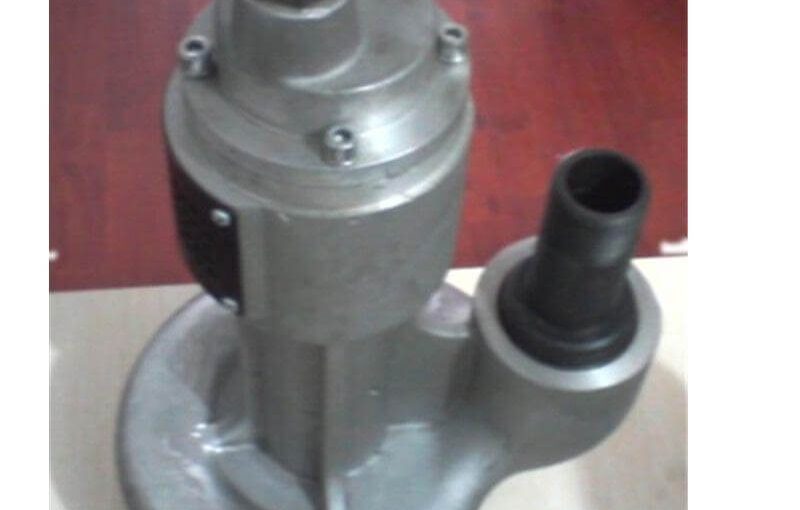
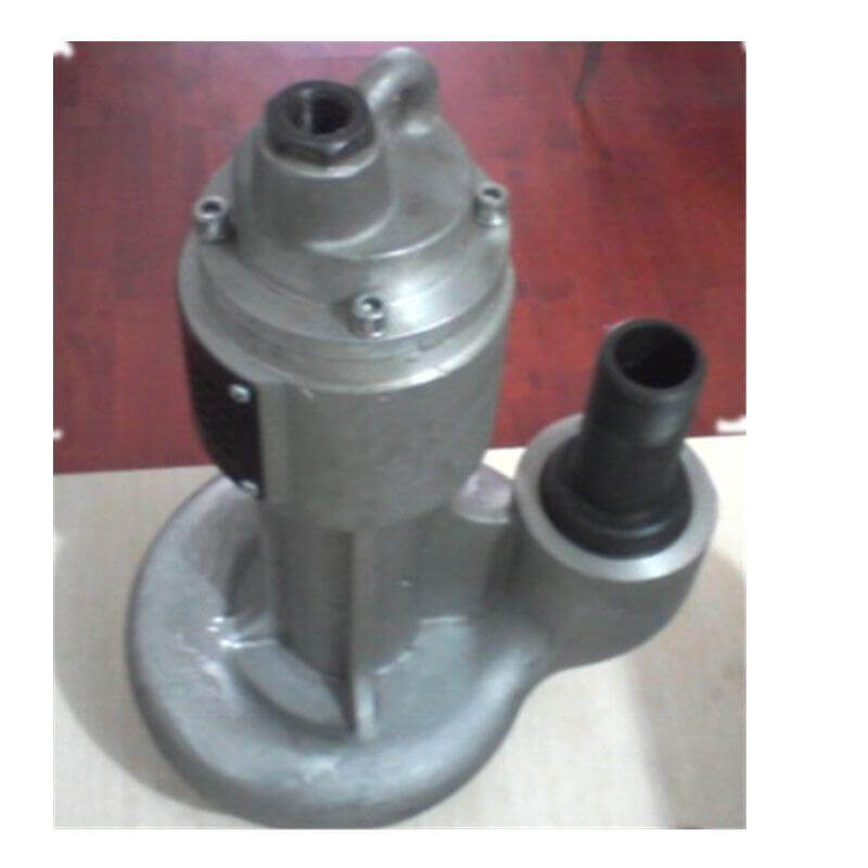
Pneumatic Submersible Pump

https://www.eu-flo.com/wp-content/uploads/2019/04/20190401160120B.jpg 

 EBB3-36 Pneumatic operation Submersible pump

   The pneumatic Submersible pump for Marine       

 EBB3-36 type pneumatic pump is a kind of explosion-proof air operation Submersible pump, EBB3-36 type pneumatic pump is widely used, safe and reliable, can work continuously, EBB3-36 type pump is pneumatic operation pump

EBB3-36 type pneumatic pump is a mechanized tool with compressed air as power medium, which has the characteristics of small volume, high efficiency, safe and reliable, and continuous operation.

EBB3-36 Pneumatic operation submersible pump is widely used in shipbuilding, coal mines, construction, power stations, chemicals and other industries of sewage, water drainage and irrigation, but also flammable, explosive and other bad work of the only ideal tool

DATA OF EBB3-36 Pneumatic Operation Submersible Pump 

Head: ≥20m

Flowrate: ≥335min

no-load speed: 6000rpm

load gas consumption: 50L/S

Air Pipe Inner Diameter: 13mm

outlet thread: G11/2in

Pump Height: 500mm

Pump Weight: 17kg


型号

Capacityunloading(r/mi n) 

Consumption(l/s)

Air Pipe Dia(m m)Thread (i n) 

Heigh(mm)

Weight(kg)
Head(m)Capacity (l/

min)

EBB3-36A>=20>=33560005013G11/250017
EBB3-36D>=20>=33560004513G11/238012
Pneumatic Submersible Pump

Centrifugal pump use Visual automatic oiler

https://www.eu-flo.com/wp-content/uploads/2019/03/images.jpg

Centrifugal pump use of Visual automatic oiler

Centrifugal pump use Visual automatic oiler

Centrifugal water pump use Visual automatic oiler


Visual automatic oiler instructions

The 1741-V visual automatic oiler is designed for long-term stable lubrication and oil supply.

The visual auto-oiler consists of a medium-duty spring (green), a light-duty spring (orange) and a heavy-duty spring (black). When used, the correct spring is selected according to the lubricant. #0-#3 grease can be used.


All models of lubricant oilers (both manual and electric) have a standard lubricant coupling for grease to the oil cup and embedded fuses to prevent overfilling or cup pressure Too high.


Description

Interface thread 1/8 NPTF

Interface (butter): standard

Capacity: 2.2 cubic inches, about 3300ml

Maximum pressure relief: 15PSI (about 1kg)

Lubricating oil pressure: see table below


Spring full cup empty cup 1. Screw the thread interface into the bearing to lubricate

337421-1 Orange 0.23kg 0.147kg Note: With a hex wrench, do not tighten the oil cup with your hand.

337421-2 Green 0.307kg 0.193kg Damaged

337421-3 Black 0.387kg 0.240kg 2. Use grease coupling to add grease

  1. Add grease to the following

Safe use specifications a. Side view if the plunger line to the lid angle is found.

  1. Please add oil to the oil cup according to the installation and operation instructions. Do not overfill b. Look down and find the indication point on the plunger to reach the red line of the cup cover.
  2. Carefully remove the lid and the lid is spring loaded.

Note: Once the oil cup is too full, too much lubricating fluid will flow out of the oiler’s lid and relieve pressure. All normal operations will be carried out.

Replace the spring:

Choose the right spring according to the grease.


Press and open the lid, then rotate the lid counterclockwise and release the pressure.

Note: The lid of the cup is equipped with a spring. It cannot be removed quickly and needs to be carefully removed.

  1. Remove the spring from the cup.
  2. Install the new spring into the cup

Note: Make sure the spring is installed in place on the cup and plunger

  1. Press and install the lid onto the oil cup and turn it clockwise until the pressure is right.


maintenance

Cleaning:

1 Remove the oiler from the bearing housing

  1. Open the lid as above
  2. Remove the spring from the cup
  3. Insert the stick into the center hexagon and push the plunger out of the cup.
  4. Gently clean the parts with a clean, soft cloth.
  5. When reinstalling, apply a layer of film on the oil cup and plunger with grease to lubricate.
  6. Press the lid under the hand and rotate it clockwise to the proper pressure.

Pump Common Faults and Troubleshooting Methods

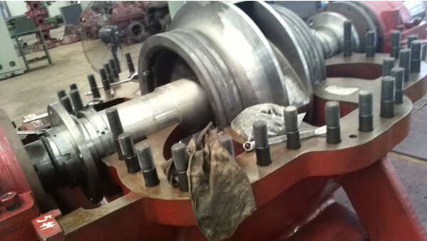
Split Case Pump Faults
SPlit Case Pump Eu-Flo

Pump Common Faults and Troubleshooting Methods

capacity no enough or no out water

1:motor reverse

2:flow channel been clogging

3:density of medium is too high

4:required head too high or the pump head selection smaller than actual required head

5:impeller been wear

6:water lever is too lower and been suction air

7:check valve installation reverse   (way adopt to trouble shooting:)

1:correction motor rotation

2:clear the Debris, set a Filter Grille near by the pump suction

3:Diluted the flow medium with water

4:try to lower required head( for example to change big diameter pipe and smoother pipe, reduce the elbow qty, or increase elbow Arc radius, or change into higher head pump)

5:change pump impeller

6:adjustment Floating ball Switch position, Make the lowest level meet the requirements of the mounting dimension diagram

7:Correct check valve direction

2.Cannot start

1.Phase deficiency

2.Impeller jammed

  1. Winding connectors or cable breakers

4:Stator winding Burnout

5:controlling electrical faults

way adopt to trouble shooting

1、check the line, eliminate the problem of missing phase

2、remove debris, it is best to set the filter around the pump (but not in the pump inlet installation filter)

3、Repair after checking with ohm meter

4、Repair after checking with ohm meter

5、repair, replacement winding or stator

6、Stator Burnout     (reason maybe caused:)

1、the lack of phase

2、Impeller jammed

3、winding joint or cable circuit breaker

4、Stator winding burnout

5、Control electrical fault     (way adopt to trouble shooting:)

1、configuration protection Control electrical appliances and: Find out the line, clear the fault; remove the dirt, tighten the impeller fastening screws and stainless steel spring washer; dilute the medium with water; rinse and dredge the cooling system

2、Replace the mechanical seal or “O” seal ring

3、Tighten the fasteners of each part

  1. Too large current (reason maybe caused:)

1、Pipes and impellers are blocked

2、pumping liquid density or viscosity is high

3、the selected pump head greatly exceeded the actual needs, or the use of changing conditions, the device head greatly reduced, so that the pump over the recommended flow operation (way adopt to trouble shooting:)

1、Clean up the blockage in the pipe and impeller

2、Change the density or viscosity of the pumping liquid

3、off the small outlet valve, reduce the flow, or trim smaller impeller, or replace the lower head pump

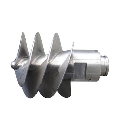
pump inducer function-multi-stage pump inducer function-centrifugal pump inducer function

https://www.eu-flo.com/wp-content/uploads/2019/03/inducer-2B.jpg

centrifugal pump inducer function


pump inducer function , multi-stage pump inducer function, centrifugal pump inducer function

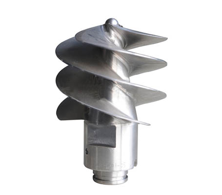
   The inducer is installed in front of the first stage impeller of the centrifugal pump. It is called the front inducer. When the liquid flows through the inducer, it works on the liquid to increase the energy. It is equivalent to adding work energy to the liquid entering the rear impeller, which is equivalent to The liquid entering the rear impeller is pressurized to increase the suction of the pump.


The centrifugal pump inducer is an axial flow impeller with a low blade load (only a few meters lift), a small blade installation angle, a small number of blades, and a dense cascade of cascades. It has high inhalation performance. The lift generated by the inducer acts to pressurize the centrifugal impeller behind, and the suction performance of the multistage centrifugal pump is improved, so that the suction speed of the centrifugal pump can reach about 3000. At present, the design method of the inducer is an empirical design method based on the test. There are usually two design methods: one is a flat cylindrical inducer design, and the other is a curved-leaf tapered inducer .

The way Analysis of axial flow pump vibration

  1. hand rotation Difficulty: Pump shaft bending, bearing wear, pump unit non concentric, impeller touch pump shell.

Elimination measures: Straightening pump shaft, adjustment or replacement of bearings, re-Alignment , re-adjustment gap.

  1. Pump shaft Swing degree large: bearing and shaft neck wear or gap is too large.

Elimination measures: Repair the shaft neck, adjust or replace the bearing.

  1. Hydraulic unbalance: impeller unbalance, centrifugal pump individual vane groove blockage or damage.

Elimination measures: Re-calibration of the impeller static balance and dynamic balance, elimination of blockage, repair or replacement of the impeller.

  1. Axial flow pump shaft power is too large: the water level of the inlet pool is too low, the impeller submerged depth is not enough, the clutter winding impeller, pump cavitation damage degree is different, impeller defect.

Elimination measures: Raise the water level of the inlet pool, reduce the installation elevation of the pump to eliminate clutter, and set up a bar grille, repair or replace the impeller.

  1. Mounting base vibration: Poor foundation stiffness or loosening or resonance of bottom angle screws.

Elimination measures: Reinforcement of the foundation, tightening the The anchor

  1. Centrifugal pump unit efficiency decreased sharply or the efficiency of axial flow pump unit decreased slightly, accompanied by cavitation noise.

Elimination measures: Change the speed of the pump, avoid the resonance area, find out the cause of cavitation, take measures to eliminate cavitation.

  1. Pump inlet and outlet pipeline Support force is relatively large.

Centrifugal Pump Eu-Flo Material Selection

Centrifugal Pump Material Selection Sheet

Part DescriptionMaterial Combination
Cast IronDuctile IronWCB1.43081.4408DuplexSuper DuplexBronze
CasingCast IronDuctile IronWCB1.43081.44081.44701.4410Bronze
impellerCast IronDuctile IronWCB1.43081.44081.44701.4410Bronze
ShaftSS 420SS304 DuplexSuper Duplex
Seal housingCast IronDuctile IronWCB1.43081.44081.44701.4410Bronze
Stationary RingWCB1.44701.44081.44101.4410

Eu-Flo Pump Developed New Model Liquid Gas Mixture Vortex Pump

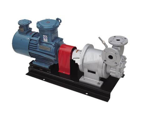
EQYB is one Magnetic drive and Vortex pump application for Gas-Liquid Mixture, the pump is basing on many years experience of the company produce Vortex Pump and improved the design. The pump adopts magnetic transmission structure, non shaft sealing, to ensure the pump no leakage when transporting liquids containing gas , after the company’s R &D team combined with the Scientific research personnel in Colleges and Universities to developed the new model that can No load, dry grinding, high temperature resistance, energy saving and environmental protection,  to turn over a new page of the history that  Magnetic drive pump can’t runing non-load. after application of Through use of a number of customers proved that the pump not only has the characteristics of small capacity with high head, but also has the advantage of magnetic driven pump without leakage, therefore it is favored by many end users. the Pump wet parts are stainless steel or other metal materials, can be non-leakage to transport flammable, explosive, poison and other dangerous liquids, precious liquids, refrigerants or high-temperature liquids, low-viscosity liquids, corrosive liquids and harsh operation and liquid containing gases, liquid gas, liquid ammonia and other easy to gasification liquid transmission. In addition, compared with the canned pump, canned pump beside to the realization of our special functions, in small capacity application we have a very special advantage. Many customer feedback, to use of our EQYB magnetic driven pump to solve for their difficult that previous canned pump can’t for of high head with small capacity. by the other hand with a smaller power and energy saving, simple and convenient operation and maintenance, occupy smaller space, long service life, greatly reducing the operating costs. it can be fully replaceable for small capacity’s canned pump applications.

Vortex Pump Liquid Gas Mixture

Flange Available for PN40,PN63, ANSI CL300,CL600